
스마트 등기구 고효율 인증 시험항목 및 기준 요약
1. 시험항목
| 번호 | 고효율 시험항목 | #1 | #2 | 비 고 | |
| 1 | 입력 전력 및 입력 전류 | ○ | * | ||
| 2 | 역률 | 기준 역률 | ○ | * | |
| 최소 역률 | ○ | * | |||
| 3 | 고조파 전류 | ○ | * | ||
| 4 | 대기 전력 | ○ | * | ||
| 5 | 상관색온도 | ○ | ○ | * | |
| 6 | 연색지수 | Ra | ○ | ○ | * |
| R9 | ○ | ○ | * | ||
| 7 | 기준 광속 | ○ | ○ | * | |
| 8 | 기준 광효율 | ○ | ○ | * | |
| 9 | 광학적 플리커 | ○ | * | ||
| 10 | 조광 특성 | 최소 광효율 | ○ | * | |
| 소음 | ○ | * | |||
| 11 | 광속 유지율 | ○ | * | ||
| 12 | 상관색온도 제어 | 최소 상관색온도 | ○ | * | |
| 최대 상관색온도 | ○ | * | |||
| 광속 변화율 | ○ | * | |||
| 13 | 표시사항 | ○ | ○ | * | |
| 비고 | 상관색온도 제어 기능 측정은 해당 기능이 내장된 제품에 한해 시험한다. | ||||
2. 고효율 인증샘플 수량
| 연번 | 품목명 | 시료의 수량 |
| 20 | 스마트LED조명 | 스마트LED등기구 = 2 |
| 측정항목 | ㅇ 기자재별 인증기술기준의 전 항목 | |
3. 스마트LED등기구 정의
AC 220 V, 60 Hz에서 유무선 통신(IR리모컨 제외)으로 에너지 절감을 위해 조광제어가 가능하고 일체형 또는 내장형 LED 광원을 적용한 등기구(단, 별도의 아날로그 조광기로만 제어되는 제품은 제외)
4. 스마트LED조명의 인증기술기준 및 측정방법
1) 스마트LED등기구
– AC 220 V, 60 Hz에서 유무선 통신(IR리모컨 제외)으로 에너지 절감을 위해 조광제어가 가능하고 일체형 또는 내장형 LED 광원을 적용한 등기구 (단, 별도의 아날로그 조광기로만 제어되는 제품은 제외)
– 구현되는 램프의 색이 단일 또는 다수의 상관색온도(2200∼6500K) 범위 내 백색광을 구현할 수 있는 제품을 대상으로 함
– 제품의 구동을 위해 네트워크 기기(게이트웨이 or 허브)와 제어기기가 반드시 필요한 경우, 이를 모두 포함하여 시료를 제출하여야 함
– 포함됨
– 독립된 하나의 등기구를 대상으로 하며 단일 전원공급장치에 복수의 등기구가 연결된 형태는 제외함
5. 성능 시험
5.1 시험 조건
1) 특별한 규정이 없는 한 시험은 10 ∼ 30℃의 주위 온도에서 항목 순으로 시험한다. 단, 광학특성 시험은 정격입력 전압 및 주파수를 인가한 후 (25 ± 3)℃의 최대 65%의 상대습도 환경을 갖는 통풍이 없는 장소에서 해야 한다.
2) 시험전압은 ±3%의 허용오차를 가질 수 있다. 전압 범위의 경우 평균값에서 측정한다.
3) 또한 전체 고조파 성분은 3%를 초과할 수 없다. 고조파 성분은 기본파를 100%로 사용해 각 고조파 성분의 r.m.s합으로 정의된다.
4) 시스템 인증을 위한 제출 시료에는 필수 기능을 확인할 수 있는 하드웨어 및 소프트웨어 일체가 포함되어야 하며, 별도의 요구사항이 없다면 조명기기는 5대로 한정한다.
5.2 스마트LED등기구 시험방법 및 인증기준
5.2.1 시험방법
1) 입력 전력 및 입력 전류
입력 전력 및 입력 전류 시험은 [그림 2]와 같이 접속하고 정격 주파수의 입력전압을 가하여 최대 기준 제어 설정에서 입력 전력 및 입력 전류를 측정한다.
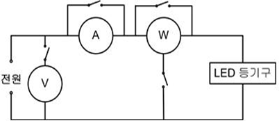
2) 역률
[그림 2]와 같이 접속하고 정격 주파수의 입력 전압을 가하여 최대 기준 제어 설정에서 기준 역률을, 최소 기준 제어 설정 상태에서 최소 역률을 다음 식에 따라 계산한다.
3) 고조파 전류
정격 주파수의 정격 전압을 가하여 최대 기준 제어 설정에서 충분히 안정된 후 고조파 전류 측정기기로 입력 측의 고조파 전류를 KS C 9610-3-2에 따라 시험한다.
4) 대기 전력
네트워크 대기 모드에서 IEC 63103에 따라 대기 전력을 측정한다.
5) 상관색온도
정격 주파수의 입력 전압을 가하여 최대 기준 제어 설정에서 KS C 0076의 측정방법에 따라 상관색온도를 측정한다.
6) 연색지수
정격 주파수의 입력 전압을 가하여 최대 기준 제어 설정에서 KS C 0075의 측정방법에 따라 연색지수(Ra, R9)를 측정한다.
7) 기준 광속
정격 주파수의 입력 전압을 가하여 최대 기준 제어 설정에서 100시간 에이징 후 배광광도계 또는 구형광속계를 사용하여 기준 광속을 측정한다.
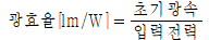
8) 기준 광효율
기준 광속 측정 시 측정된 광속 및 입력 전력으로 계산한다.
9) 광학적 플리커
정격 주파수의 입력 전압을 가하여 최대 및 최소 기준 제어 설정에서 램프가 점등된 후 충분히 안정된 상태에서 IEC TR 61547-1에 따라 PstLM을 측정하고 IEC TR 63158에 따라 SVM을 측정한다.
10) 조광 특성
① 최소 광효율
정격 주파수의 입력 전압을 가하여 최대 기준 제어 설정에서 등기구가 점등된 후 충분히 안정된 상태에서 최소 기준 제어 설정으로 제어하여 배광광도계 또는 구형광속계로 광효율을 측정한다.
② 소음
정격 주파수의 입력 전압을 가하여 최대 기준 제어 설정에서 등기구가 점등된 후 충분히 안정된 상태에서 KS I ISO 3745에 따라 측정한다. 이어서 등기구를 최소 기준 제어 설정으로 제어하여 같은 방법으로 측정한다.
11) 광속 유지율
기준 광속 측정 시간을 포함하여 등기구에 정격 전압을 인가하여 최대 기준 제어 설정에서 2,000시간 에이징 후 배광광도계 또는 구형광속계를 사용하여 광속 및 광색을 측정한다.
다만, ‘[부록 1] 광속유지율 시험을 면제받기 위한 LED패키지 시험방법 및 기준’에 따라 당해 품목 광속유지율 기준 이상의 LED패키지를 적용할 경우 광속유지율 시험을 면제할 수 있다.
12) 상관색온도 제어
① 최소 상관색온도
정격 주파수의 입력 전압을 가하여 최대 기준 제어 설정에서 상관색온도를 가장 낮게 제어하여 KS C 0076의 측정방법에 따라 상관색온도를 측정한다. 단, 상관색온도가 2 200K 미만으로 제어가 가능한 제품의 경우 최소 상관색온도를 (2 238 ± 102)K 범위로 제어하여 시험한다.
② 최대 상관색온도
정격 주파수의 입력 전압을 가하여 최대 기준 제어 설정에서 상관색온도를 가장 높게 제어하여 KS C 0076의 측정방법에 따라 상관색온도를 측정한다.
③ 광속 변화율
최대 및 최소 상관색온도 조건에서 배광광도계 또는 구형광속계를 사용하여 광속을 측정한다.
6. 인증기술기준
1) 입력 전력 및 입력 전류
최대 기준 제어 설정에서 측정한 입력 전려 및 입력 전류가 표시값의 ± 10% 범위이어야 한다.
2) 역률
기준 역률은 0.9 이상이며, 최소 역률은 0.7 이상이어야 한다. 단, 최대 기준 제어 설정에서 입력 전력이 5 W 이하인 경우 기준 역률만 측정하며 0.85 이상이어야 하고 최소 기준 제어 설정에서 입력 전력이 5 W 이하인 경우 최소 역률은 0.6 이상이어야 한다.
3) 고조파 전류
KS C 9610-3-2에 따라 시험하고 해당 규격의 허용기준을 만족하여야 한다.
4) 대기 전력
대기 전력은 1.5 W 이하이어야 한다.
5) 상관색온도
측정된 상관색온도가 <표 4>에 적합하여야 한다.
| 상관색온도 및 Duv 기준 | |||
| 공칭 상관색온도 (K) | 상관색온도 공차 범위 (K) | 기준 Duv | Duv 공차 범위 |
| 2200 | 2238 ± 102 | 0.0000 | |
| 2500 | 2460 ± 120 | 0.0000 | |
| 2700 | 2725 ± 145 | 0.0000 | |
| 3000 | 3045 ± 175 | 0.0001 | |
| 3500 | 3465 ± 245 | 0.0005 | |
| 4000 | 3985 ± 275 | 0.0010 | |
| 4500 | 4503 ± 243 | 0.0015 | |
| 5000 | 5029 ± 283 | 0.0020 | |
| 5700 | 5667 ± 355 | 0.0025 | |
| 6500 | 6532 ± 510 | 0.0031 | |
| 가변 상관색온도 (2200-6500) | |||
| 1) TF는 10개의 공칭 상관색온도를 포함하는 100 K 간격의 상관색온도를 선택 2) | |||
6) 연색지수
Ra는 80 이상이어야 하고 R9은 0 이상이어야 한다.
7) 기준 광속
표시값의 95% 이상이어야 한다.
8) 기준 광효율
<표 5>에 적합하여야 한다.
| 구분 | 입력 전력 | 광효율 (lm/W) |
| 실내용 | 10 W 이하 | 100 이상 |
| 10 W 초과 30 W 이하 | 110 이상 | |
| 30 W 초과 60 W 이하 | 115 이상 | |
| 60 W 초과 | 120 이상 | |
| 실외용 | 125 이상 | |
9) 광학적 플리커
PstLM은 모두 1.0 이하이어야 한다. SVM은 측정값 중 높은 값을 성적서에 기재하도록 한다. (PstLM은 적부 판정, SVM은 기록)
10) 조광 특성
① 최소 광효율
80 lm/W 이상이어야 한다.
② 소음
소음은 측정값 모두 24 ㏈ 이하이어야 한다.
11) 광속 유지율
광속 유지율은 기준 광속 대비 95% 이상이어야 한다. 광색변화 은 0.007 이하이어야 한다.
12) 상관색온도 제어
① 최소 상관색온도
측정된 최소 상관색온도가 <표 4>에 적합하여야 한다.
② 최대 상관색온도
측정된 최대 상관색온도가 <표 4>에 적합하여야 한다.
③ 광속 변화율
기준 광속 대비 20% 이상이어야 한다.
13) 표시사항
제조자는 제품 또는 사용설명서에 다음 사항을 반드시 표시하여야 한다.
1) 고효율 인증번호, 고효율마크 :
2) 품목명(실내용/실외용) 및 모델명 :
3) 정격 전압, 주파수 :
4) 정격 전력 :
5) 대기 전력 :
6) 정격 전류 :
7) 기준 광속 :
8) 기준 광효율 :
9) 조광 가능 여부 : 제품 및 포장에 조광 가능 여부 표시
10) 연색지수 :
11) 원산지 표시(상표, 제조자명, 공급자명) :
12) KC 및 KS에서 요구하는 필수 사항 :
13) A/S 연락처 :
14) 제조연월 :
15) 통신 및 제어방식 :
16) 상관색온도 : 상관색온도 제어가 가능한 제품의 경우 포장에 스케일 금리과 수치로 제어 범위를 표시
예시) 3 000K 또는
17) 공장초기화 방법 : 포장 및 사용설명서에 표시
[부록 1] 광속유지율 시험을 면제받기 위한 LED패키지 시험방법 및 기준
1. 스마트LED등기구 시험면제조건
1) 스마트LED등기구의 광속유지율 시험을 면제받기 위한 LED패키지에 대한 광속유지율시험은 아래의 2. LED패키지 시험방법 및 기준을 적용한 고효율인증 시험기관의 성적서 또는 본 기준의 시험방법 동등 이상의 기준을 적용한 공인된 시험기관의 성적서를 인정하며, 광속유지율 시험성적서의 측정값은 2. LED패키지 시험방법 및 기준의 기준값 이상이어야 한다.
* 단 LED 패키지의 경우 시험성적서를 통해 모델명을 정확히 확인할 수 있어야 하며, 모델명을 통해 광속, 상관색온도, 연색지수를 구분할 수 있어야 한다. 또한 시험성적서는 발행일 기준 3년 이내이어야 한다.2) 스마트LED등기구의 LED패키지에서 측정된 온도 및 전류는 패키지 성적서에 기재된 온도 및 전류 이하이어야 한다
Summary of test items and criteria for high-efficiency certification of smart lighting fixtures
1. Test item
| No. | High-efficiency test items. | #1 | #2 | 비 고 | |
| 1 | Input power and input current | ○ | * | ||
| 2 | Power factor | Standard power factor. | ○ | * | |
| Minimum power factor | ○ | * | |||
| 3 | Harmonic current | ○ | * | ||
| 4 | Standby power | ○ | * | ||
| 5 | Correlated color temperature | ○ | ○ | * | |
| 6 | Color rendering index (CRI). | Ra | ○ | ○ | * |
| R9 | ○ | ○ | * | ||
| 7 | Standard luminous flux | ○ | ○ | * | |
| 8 | Standard luminous efficiency | ○ | ○ | * | |
| 9 | Optical flicker | ○ | * | ||
| 10 | Dimming characteristics | Minimum luminous efficiency | ○ | * | |
| Noise | ○ | * | |||
| 11 | Lumen maintenance | ○ | * | ||
| 12 | Correlated color temperature control | Minimum correlated color temperature | ○ | * | |
| Maximum correlated color temperature | ○ | * | |||
| Luminous flux variation | ○ | * | |||
| 13 | Mark(ing) | ○ | ○ | * | |
| Remark | The measurement of correlated color temperature control function is tested only for products equipped with the function | ||||
2. Quantity of high-efficiency certification samples
| Product name | Requested Sample Q’ty | |
| SMART LED Fixture | SMART LED Fixture = 2 | |
| Measurement item(s) | Overall criteria for certification technology standards by equipment type | |
3. Definition of Smart LED Lighting Fixture
A lighting fixture that applies a built-in or integrated LED light source and enables dimming control for energy-saving through wireless communication (excluding IR remote control) at AC 220 V, 60 Hz. However, products that are controlled only by a separate analog dimmer are excluded.
4. Certification Technology Standards and Measurement Methods for Smart LED Lighting
1) Smart LED Lighting Fixture
A lighting fixture that applies a built-in or integrated LED light source and enables dimming control for energy-saving through wireless communication (excluding IR remote control) at AC 220 V, 60 Hz. However, products that are controlled only by a separate analog dimmer are excluded.
Products that can implement white light within a single or multiple correlated color temperature (2200 to 6500 K) range are subject to certification.
If both a network device (gateway or hub) and a control device are necessary for operating the product, both must be included when submitting the sample.
Products with built-in sensors are also included in Smart LED Lighting Fixtures.
The certification targets an independent lighting fixture, and products that connect multiple lighting fixtures to a single power supply unit are excluded.
5. Performance Test
5.1 Test Conditions
Unless otherwise specified, the test shall be performed in the order of items at ambient temperature between 10℃ and 30℃. However, for the optical characteristic test, the test must be conducted in a non-ventilated place with a maximum of 65% relative humidity at (25 ± 3) ℃ after applying rated input voltage and frequency.
The test voltage may have a permissible error of ±3%. In the case of a voltage range, it shall be measured from the average value.
Moreover, the total harmonic distortion shall not exceed 3%. The total harmonic distortion shall be defined as the R.M.S sum of each harmonic component using the fundamental wave as 100%.
The sample submitted for system certification must include a hardware and software unit that can confirm essential functions, and unless otherwise specified, the lighting equipment shall be limited to 5.
5.2 Smart LED Lighting Fixture Test Methods and Certification Standards
5.2.1 Test Method
■ Input power and input current
The test for input power and input current is conducted by connecting as shown in [Figure 2] and measuring the input power and input current at the maximum standard control setting by applying the input voltage of the rated frequency.
Figure 1
■ Power factor
Connect as shown in [Figure 2] and calculate the reference power factor at the maximum standard control setting and the minimum power factor at the minimum standard control setting using the following equation, by applying the input voltage of the rated frequency.
Figure 2
■ Harmonic current
Measure the harmonic current on the input side using a harmonic current measuring instrument according to KS C 9610-3-2, after sufficient stabilization at the maximum standard control setting with the rated voltage of the rated frequency.
■ Standby power
Measure the standby power according to IEC 63103 in the network standby mode.
■Correlated color temperature
Measure the correlated color temperature according to the measurement method of KS C 0076 at the maximum standard control setting by applying the input voltage of the rated frequency.
■ Color rendering index (CRI)
Measure the color rendering index (Ra, R9) according to the measurement method of KS C 0075 at the maximum standard control setting by applying the input voltage of the rated frequency.
■ Standard luminous flux
Measure the standard luminous flux using a photometer or an integrating sphere spectrometer after 100 hours of aging at the maximum standard control setting by applying the input voltage of the rated frequency.
■ Standard luminous efficacy
Calculate the standard luminous efficacy using the measured luminous flux and input power during the measurement of the standard luminous flux.
Figure 3
■ Optical flicker
With the rated frequency input voltage, after the lamp is turned on and sufficiently stabilized, measure PstLM according to IEC TR 61547-1 at maximum and minimum reference control settings, and measure SVM according to IEC TR 63158.
■ Dimming characteristics
① Minimum luminous efficacy: With the rated frequency input voltage, after the luminaire is turned on and sufficiently stabilized, control it with the minimum reference control setting and measure the luminous efficacy with a photometer or a spherical illuminance meter.
② Noise: With the rated frequency input voltage, after the luminaire is turned on and sufficiently stabilized, measure the noise according to KS I ISO 3745. Then, control the luminaire with the minimum reference control setting and measure the noise in the same manner.
■ Luminous maintenance
Apply the rated voltage to the luminaire and measure the luminous intensity and chromaticity with a photometer or a spherical illuminance meter after 2,000 hours of aging at the maximum reference control setting, including the standard luminous intensity measurement time.
However, if the LED package applied to the product meets the luminous maintenance standard according to the “Test method and standard for LED package to be exempted from luminous maintenance test [Appendix 1]”, the luminous maintenance test can be exempted.
■ Control of Correlated Color Temperature
①Minimum correlated color temperature
The correlated color temperature is measured according to the measurement method of KS C 0076 by controlling the correlated color temperature at the lowest level in the maximum standard control setting by applying the input voltage of the rated frequency. However, for products that can be controlled to a correlated color temperature of less than 2,200K, the minimum correlated color temperature is tested by controlling it within the range of (2,238 ± 102)K.
②Maximum correlated color temperature
The correlated color temperature is measured according to the measurement method of KS C 0076 by controlling the correlated color temperature at the highest level in the maximum standard control setting by applying the input voltage of the rated frequency.
③Flux variation rate
The luminous flux is measured using a photometer or a spherical flux meter under maximum and minimum correlated color temperature conditions.
6. Certification Technical Standards
■ Input power and input current
The measured input power and input current at the maximum standard control setting should be within ±10% of the indicated value.
■ Power factor
The standard power factor should be 0.9 or higher, and the minimum power factor should be 0.7 or higher. However, if the input power is 5W or less at the maximum standard control setting, only the standard power factor is measured, which should be 0.85 or higher. If the input power is 5W or less at the minimum standard control setting, the minimum power factor should be 0.6 or higher.
■ Harmonic current
The test should be conducted according to KS C 9610-3-2 and meet the allowable criteria of the corresponding specification.
■Standby power
The standby power should be 1.5W or less.
■Correlated color temperature
The measured correlated color temperature should be suitable for <Table 4>.
| Color temperature and Duv criteria for correlation. | |||
| Nominal correlated color temperature (K) | Correlated color temperature tolerance range (K) | Standard for Duv | Duv tolerance range |
| 2200 | 2238 ± 102 | 0.0000 | |
| 2500 | 2460 ± 120 | 0.0000 | |
| 2700 | 2725 ± 145 | 0.0000 | |
| 3000 | 3045 ± 175 | 0.0001 | |
| 3500 | 3465 ± 245 | 0.0005 | |
| 4000 | 3985 ± 275 | 0.0010 | |
| 4500 | 4503 ± 243 | 0.0015 | |
| 5000 | 5029 ± 283 | 0.0020 | |
| 5700 | 5667 ± 355 | 0.0025 | |
| 6500 | 6532 ± 510 | 0.0031 | |
| Variable correlated color temperature (2200-6500) | |||
| 1) TF는 10개의 공칭 상관색온도를 포함하는 100 K 간격의 상관색온도를 선택 2) | |||
<Table 4>
■ Color rendering index (CRI)
Ra should be 80 or higher and R9 should be 0 or higher.
■ Standard luminous flux
It should be 95% or higher of the indicated value.
■ Standard luminous efficacy
It should meet the requirements of <Table 5>.
| Index | Input power | Lumen efficiency (lm/W) |
| Indoor | 10 W or less | 100 or higher |
| More than 10W ~ less than 30W | 110 or higher | |
| More than 30W ~ less than 60W | 115 or higher | |
| More than 60W | 120 or higher | |
| Outdoor | 125 or higher | |
■ Optical Flicker
PstLM must be less than or equal to 1.0. SVM should record the highest measurement value in the performance report. (PstLM for acceptance judgment, SVM for recording)
■ Optical Characteristics
① Minimum Luminous Efficacy
It should be 80 lm/W or higher.
② Noise
The noise should be below 24 dB for all measurements.
■ Luminous Maintenance Factor
The luminous maintenance factor should be 95% or higher compared to the reference luminous flux. The chromaticity change should be 0.007 or less.
■ Correlated Color Temperature Control
① Minimum Correlated Color Temperature
The measured minimum correlated color temperature must be suitable according to <Table 4>.
② Maximum Correlated Color Temperature
The measured maximum correlated color temperature must be suitable according to <Table 4>.
③ Luminous Flux Variation
It should be 20% or more compared to the reference luminous flux.
■Markings
The manufacturer must indicate the following items on the product or user manual:
High Efficiency Certification Number, High Efficiency Mark:
Product Name (Indoor/Outdoor) and Model Name:
Rated Voltage, Frequency:
Rated Power:
Standby Power:
Rated Current:
Reference Luminous Flux:
Reference Luminous Efficacy:
Dimming Capability: Indicate dimming capability on the product and packaging.
Color Rendering Index:
Country of Origin (Trademark, Manufacturer Name, Supplier Name):
Mandatory requirements in KC and KS:
A/S Contact:
Manufacturing Year and Month:
Communication and Control Method:
Correlated Color Temperature:
Setting Reset Method: Indicate on the packaging and user manual.
[Appendix 1]
LED Package Test Method and Standard for Exemption from Luminous Maintenance Factor Test
Exemption Criteria for Smart LED Luminaire Testing
To exempt the luminous maintenance factor test of a smart LED luminaire, the luminous maintenance factor test for the LED package should meet the criteria in the LED Package Test Method and Standard in section 2 below, and the performance report from a certified testing agency that applies criteria equivalent to or higher than the test method in this standard, or the performance report from a certified testing agency that applies the test method in this standard, must be accepted. The measurement value in the luminous maintenance factor test report must be equal to or higher than the standard value in the LED Package Test Method and Standard in section 2.
However, for LED packages, the model name must be accurately confirmed through the test performance report, and the luminous flux, correlated color temperature, and color rendering index must be distinguishable through the model name. The test performance report must also be issued within 3 years of the date of issue.The temperature and current measured from the LED package in the smart LED luminaire should be lower than or equal to the temperature and current specified in the package performance report.